Bandspread calculator
 In amateur radio practice, the problem often turns up of creating a receiver for one narrow SW band with a small ratio of the maximum frequency to the minimum. However, variable capacitors available to radio amateurs have a limited fixed set of factors of the maximum capacitance to minimum ratio. As a result, the frequency range of the LC-circuit, which includes such a capacitor, is also fixed and usually wider than necessary. At the same time, a narrow working range occupies only a small part of the receiver dial, which is very inconvenient. To stretch the working range to the full scale you can connect in parallel and in series with the variable capacitor of the so-called bandspread capacitors. The Coil64 program allows you to calculate such capacitors.
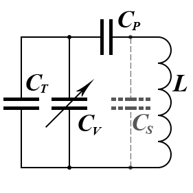
When calculating, the initial data are the maximum and minimum capacitance of the variable capacitor Cv, as well as the minimum and maximum frequency of the working range. The value of the stray mounting capacitance Cs of the circuit layout, which is also taken into account, has a significant effect on the calculation result. With different sets of input data, two options are possible:
 The available tuning variable capacitor is not able to overlap the specified frequency range. You need to choose another one or reduce the working range.
- Frequency overlap is possible. However, it is clear that in this case the inductance value of the circuit cannot be arbitrary and is determined by the W.Thomson's formula, taking into account the possible capacitance values of all the circuit capacitors. The permissible range of inductance values is shown in a tip next to the input box.
At the reverse calculation, instead of the exact calculated capacitance values of the series and parallel capacitors, the closest from the standard E24 series are substituted. They can be chosen so that the working frequency range simply fits in the receiver dial. Otherwise, both series CP and parallel CT additional capacitance should be made from the parallel connection of fixed and tuning capacitors to get the calculated values.
At the direct calculation, the question remains. What value of inductance should be taken from the range proposed by the program? The answer to this question depends on the appropriation of the tuned LC-circuit. If this circuit is the input circuit of the receiver, then for the minimum noise figure, and therefore for maximum sensitivity, you should create a circuit with minimal loss or with a maximum quality factor. The Q-factor of a parallel LC-circuit depends on the ratio of its characteristic impedance to the loss resistance.
 It would seem that at the maximum inductance value there will be a maximum Q-factor value, but this is not so. With maximum inductance, a large coil should be used. Loss in this case increases faster than the characteristic impedance and such LC-circuit will not have the highest possible Q-factor. The optimum, as always, is somewhere in the middle. Practitioners suggest choosing the inductance based on the LC-circuit characteristic impedance value in the range of 300 ... 500 Ohms. The Coil64 program allows you to make this choice.
If the circuit is used in a generator, then the frequency stability criterion comes first. In this case, the inductance value is recommended to choose the minimum possible, provided that the generator is stable.
Reference:
- Online Bandspread Calculator - Copyright 2013, 2016 Robert Weaver;
- Bandspread Calculations. The base theory and equations - (parts 1...4) Copyright 2009, 2021 Robert Weaver;