Inductance, Q-factor and self-capacitance of a ferrite toroid coil at radio frequencies
 The use of ferrite cores can significantly reduce the dimensions of the inductive elements. At the same time, with appearance of new high-frequency ferrites, radio amateurs are increasingly using ferrite toroid cores to make the LC resonant filters. Since the magnetic permeability of ferrite and its losses essentially depend on the frequency, this occasion must be taken into account when calculating the inductance of such coils at radio frequencies. To do this, the relative magnetic permeability of ferrite is presented as a complex value:
 |
[1] |
In this case, the real part of this value μ' corresponds to the usual concept of magnetic permeability, which takes into account how many times the magnetic flux density in ferrite increases. And the imaginary part of μ'' takes into account the losses in the ferrite.
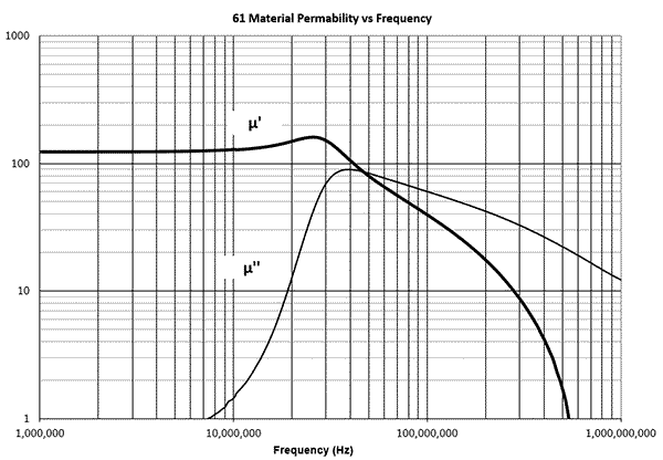 Many manufacturers publish graphs and tables of the complex magnetic permeability of ferrite versus frequency. You can find it in datasheets and put manually in the corresponding input fields in the Coil64 program. The complex magnetic permeability data of some common ferrite materials are automatically inserted from the adapted official Fair Rite tables in csv format. The data are approximated for working frequency using the cubic spline approximation method. Torus sizes can be set manually or selected from a standard range.
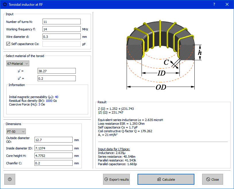
Since the losses in the ferrite are an order of magnitude higher than the conductor losses, the last can be ignored. To calculate the impedance of such a coil, we will make the appropriate substitutions in the impedance formula. We take the value of inductance L from here (formula [3]), and the relative magnetic permeability μr from the expression above (all measurements are in SI units):
 |
[2] |
The vector diagram shown below can help to visualize the behavior of a ferrite core coil at different frequencies. At relatively low frequencies, the losses in the ferrite are small and the relative magnetic permeability is close to the initial permeability of the ferrite (vector 2 in the diagram). The Q factor of a coil can be defined as the ratio of the reactive to the active part of its impedance or, after simplification, as the ratio of the real to the imaginary part of the complex magnetic permeability of ferrite.
 |
[3] |
At relatively low frequencies, the Q factor is very high. With increasing frequency, the losses increase and the active part of the impedance can exceed the reactive one, while the Q-factor of the coil tends to zero (vector 3 in the diagram). If the coil is used as an RF choke, this fact does not really matter. It is only necessary that the coil impedance modulus | Z | remained high enough. However, there is no sense to use such a coil as a LC resonant circuit coil.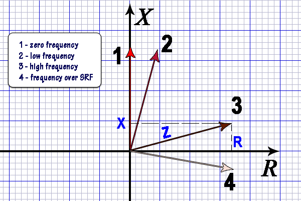 With a further increasing frequency, both parts of the complex magnetic permeability decrease significantly, which generally makes it senseless to use ferrite at these frequencies. These cutoff frequencies are different for different ferrite materials. Some materials can be used in resonant coils at frequencies up to tens of megahertz, as well as in chokes, common mode suppression devices, and broadband transformers up to hundreds of megahertz.
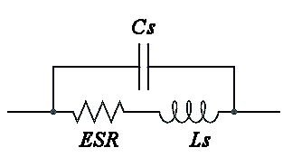
Do not forget about the parasitic coil self-capacitance Cs. The value of Cs is estimated automatically by G3RBJ formulas [ref.5 below]. When the coil is used as part of a parallel resonant LC circuit, the coil usually operates at frequencies much lower than the self-resonance frequency, and its self-capacitance could be added to the circuit capacitance. In this case, when calculating, it is useful to set the self-capacitance Cs equal to zero. To do this, uncheck the box for self-capacitance, then you can manually set any Cs value.
If the coil is used as part of a series LC resonant circuit or as a choke, for the correct impedance calculation, it is necessary to take into account the coil stray self-capacitance checking the corresponding check-box or putting the Cs value manually. If the reactive part of the impedance according to the results of the calculation becomes negative (vector 4 in the diagram), then the coil operates above the self-resonance frequency and has a capacitive reactance instead of an inductive one, which is highly undesirable.
All of the above is true only under the following conditions:
- Ferrite core should work in low fields with a flux density much lower than the saturation flux density, at the initial part of the magnetization curve, more on this here;
- The working temperature of the ferrite should be less Curie temperature;
- Ferrite core should work without the volume resonance phenomenon;
Related links:
- Calculate ferrite cored inductor - rectangular cross section - Owen Duffy (VK2OMD ex VK1OD) online calculator;
- Inductance of RF cored inductors and transformers - Owen Duffy [PDF];
- Calculation of impedance of a ferrite toroidal inductor – from first principles - Owen Duffy;
- The Self-Capacitance of Toroidal Inductors - G3YNH;
- The Self-capacitance of single layer toroidal inductors with ferrite cores - G3RBJ.