Maxwell's method for calculation of the foil-wound and flat spiral coils
Many thanks to Robert Weaver for his help in preparing this material
 Both a flat spiral coil and a coil wound with thin foil in the Coil64 program are calculated using the Maxwell's method of infinitely thin circular filament (hereinafter referred to as the Maxwell model). Using the example of these two coils, we can examine in more detail the features of this method. Maxwell is famous for the fact that in his treatise "Electricity and Magnetism" he theoretically predicted the existence of electromagnetic waves and light is also an electromagnetic wave. But in the same treatise, he created the theoretical basis for calculating inductance. Maxwell deduced the mutual induction formula between two infinitely thin coaxial circular filaments:
- M - mutual induction of two circular filaments with the same current;
- r1, r2 - the radii of two infinitely thin circular filaments with current;
- x - the distance between the centers of the circles bounded by these filaments;
- K(k),E(k) - Elliptic_integral, respectively, of the first and second kind, the calculation of which by numerical methods does not require large computational resources;.
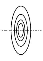 Using this method, any round coil can be represented as a collection of such filaments. In this case, both of our coils are modeled as an array of concentric rings of such filaments (x = 0). The number of these rings is equal to the number of turns of the coil. However, with such a transformation of a real conductor with a certain cross-section into an infinitely thin filament, we need to determine what the distance between these virtual filaments is equal to. What distance should I take if the cross-sectional figure of a wire takes up a certain area? Maxwell showed that this distance is equal to the geometric mean distance (GMD) between all points of the cross section of the two conductors and that in the case of a round wire, this distance is simply equal to the distance between the centers (axes) of the wire. The radius of this filament is also considered from the axis of the winding to the axis of the real wire. Thus, the conversion of a real coil into a Maxwell's model in the case of a wire of circular cross section is quite simple:
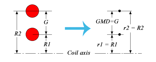
But how to calculate the self-inductance of an single turn? Maxwell showed that this inductance is equal to the mutual induction of two virtual filaments with the same diameter, located at a certain distance. This distance also depends on the shape of the cross section figure of the wire and was called the geometric mean distance of this figure "from itself." For a round wire, this distance is:  Where rw - cross-section radius of the wire.ТThus, to calculate the inductance of a Tesla's flat spiral coil by the Maxwell's method, we know all the arguments of the formula and their relationship with the actual dimensions of the coil. We will have to calculate the self-inductance of each turn and the mutual induction between each pair of turns, and then, since all magnetic fluxes are summed, we have to summarize all these results. In passing, we note that in this way it is possible to calculate the inductance of any round coil, for example a multi-layer.
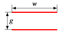 If the cross section of the wire is not round, then GMD is no longer equal to the distance "from center to center" of the wire. Moreover, it depends not only on the shape of the section, but also on the relative position of such conductors. Therefore, the calculation of the inductance of the coil wound with foil is much more complicated. We add one more simplification and present the cross section of the foil in the form of an infinitely thin line. In [2], it was shown that GMD between two such parallel lines is determined by the following expression:
Thus, the distance between two virtual filaments (GMD) is not equal to the distance between the centers of the real turns of the foil (g), but has a complex dependence on this distance and on the width of the foil. Moreover, given this fact, we have to adjust the radii of these filaments. They are also not equal to the distance from the axis of the coil to the center of the foil. The transformations into the Maxwell's model are not identical for two different pairs of foil turns, therefore, in the calculation algorithm, we are forced to calculate the GMD and filament radii separately for each such pair. 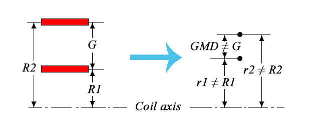
 When calculating the self-inductance of a single turn as the radii of the virtual filaments, we take the distance from the axis of the coil to the center of the foil and the GMD of an infinitely thin line "from itself", which is calculated by the following formula:
In the sequel, the algorithm for calculating the total inductance of the foil-wound coil does not differ from that for a flat spiral coil wound with a round wire.
Of particular note are the limitations in the calculations. There are several of limitations:
- Firstly, the simplification of real geometry to infinitely thin objects already introduces a certain error. But it is small enough, otherwise such a simplification would not make sense. There are only two significant limitations. The diameter of the winding should be larger than the lateral dimensions of the wire. For wire coils, this condition is most often kept in practice. It is difficult to imagine a coil with a winding diameter comparable to the wire diameter. As for the foil-wound coil, the width of the foil can be any. If the width of the foil is not larger than the diameter of the winding, then the error is within 10%. With a wider foil, the error becomes unacceptable. Therefore, this method is suitable only for estimate. Unfortunately, it will not be possible to calculate the inductance of a kitchen foil roll using this method, and electromagnetic simulators will have to be used to calculate such a coil. For example ANSYS MAXWELL 3D with Magnitostatic solver. The second limitation is the ratio of the width of the foil to its thickness should be at least 100. In this case, we can consider it close enough to an infinitely thin line, as in the model described above.
- The second limitation is that the current density at each point in the cross section of the conductor is assumed to be the same. This is true only for direct current. With alternating current, a skin effect takes place. However, at relatively low frequencies, the error introduced by this effect is quite small.
- The third limitation is that the current density along the length of the conductor is also assumed the same. In other words, the same current flows in each filament of our model. This is also true only for DC, and at relatively low frequencies, differences from DC are not significant and are not taken into account.
In conclusion, we draw your attention to the fact that the GMD between two round wires will always be equal to the distance between their axes, regardless of their relative position. In the case of foil, this is not so. If two flat conductors are located not on top of one another, but in co-line, then the GMD between them will be determined by another formula and the calculation algorithm will change again [3]. For wires with a different cross-sectional profile, we will also have to re-calculate the arguments for the Maxwell's formula taking into account the shape of this profile and the relative position of the wires.
Related links:
- Geometric Mean Distance — Its Derivation and Application in Inductance Calculations - Robert Weaver, Saskatoon, Canada (PDF);
- Formulas and Tables for the Calculation of Mutual and Self Induction. E B Rosa & F W Grover, revised 1916 3rd edition, 1948 (PDF);
- On the Geometrical Mean Distance of two figures in a plane. J C Maxwell, Trans Roy. Soc. Edinburgh, Vol 26, 1872 (PDF).