Optimal multilayer coil for the audio filters is a Brooks coil
 Calculation of a multilayer inductor in the Coil64 app uses a universal algorithm based on J.K. Maxwell's formula for mutual induction of circular turns. This algorithm makes it possible to enough accurately calculate a multilayer coil with any ratio of the width, length and diameter of the winding. However, of particular interest to radio amateurs are the so-called optimal multilayer coils with minimal losses, which are used in loudspeaker filters. In this regard, the question arises: "What geometry of the winding has the maximum possible inductance for a given wire length?" As a result, losses in this coil are also minimal. And the cost of the wire also plays an important role. Let's imagine that we have a certain fixed length of wire and we need to wind a coil with maximum inductance. What needs to be done for this?
- First of all, the turns of the winding should be located as close to each other as possible. Then their mutual induction, which makes a significant contribution to the total inductance of the coil, is also maximum. This condition is met if the cross-section of the winding is round. In practice, it is rather problematic to make such a winding of a multilayer coil with a large number of turns, therefore, a square section is used. It is only 1.1% poor to the round one in terms of efficiency.
- Secondly, the inductance of each turn is directly proportional to its diameter, so we need the largest possible winding diameter to get the maximum inductance.
The figure below shows a cross-section of four coils. To wind each of them, a wire of the same length is used, but the diameter of the winding is different. The outermost coil on the left meets all of the above requirements, but is not optimal. Since the inductance of the winding is usually proportional to the square of the number of turns, the left coil will not have a high inductance, because as the diameter increases, we simply do not have enough wire for a large number of turns. The coil on the far right has many turns, but it is also not optimal for two reasons. The diameter of each turn is small (especially in the starting layers of the winding), which results in low inductance per turn. In addition, the distance between the extreme turns along the diagonals of the winding section is large. This leads to weak mutual induction between them. As a result, the proportionality of the inductance to the square of the number of turns is violated and the total inductance in this case is also far from the maximum possible.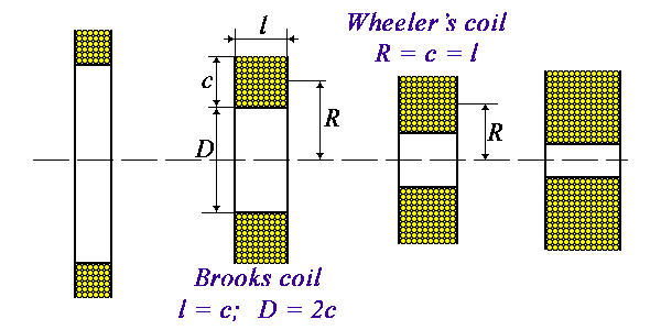 Obviously, the optimum lies somewhere in the middle. For the first time, the parameters of such an optimal coil were calculated by J.K Maxwell back in the 19th century. He identified such a coil at a ratio of 2R / c = 3.7. In 1931, H.B. Brooks wrote an article in which he refined Maxwell's calculations and calculated the ideal dimensions for such an optimal coil of 2R / c = 2.967. Or more simply: R = 3c / 2. Or even simpler: l = c, D = 2c. This optimal multilayer coil is called a Brooks coil. He derived a simple formula for calculating the inductance of such an optimal coil:
 |
[1] |
It is this coil that is recommended as an ideal option for an acoustic filter.
Please note that the most famous formula for calculating multilayer coils calculates the so-called Wheeler's coil. It is somewhere similar to a Brooks coil, but must satisfy the condition R ≈ c ≈ l and therefore is not optimal.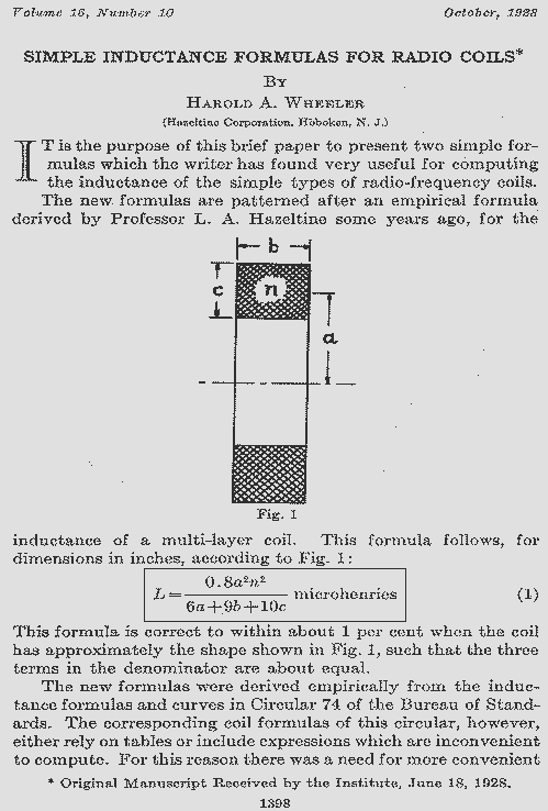
For a specific inductance and wire diameter, there is just one size option for such a coil. The Coil64 module for calculating the optimal multilayer coils allows you to calculate a table of Brooks coils with options for sizes for different wire diameters. In the table, by right-clicking on the header, you can hide unnecessary table columns.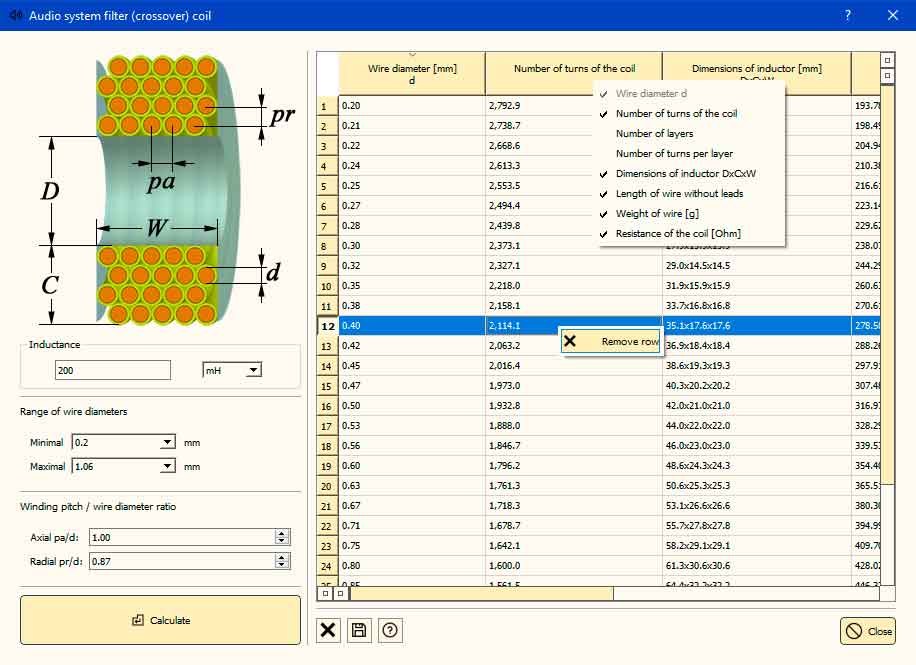 In the same way, you can remove unnecessary rows from the calculation. The results can be saved to a CSV file.
Another important point when calculating the inductance of such a coil is taking into account the so-called winding density. In the main window of the program, it is assumed that the multilayer coil has a so-called layer-by-layer winding. This is when the turn of the next layer is located directly above the turn of the previous one. In practice, more often, especially if the winding is of a sufficiently large wire diameter, the turns of the next layer fall into the grooves between the turns of the previous one. This is called orthocyclic winding.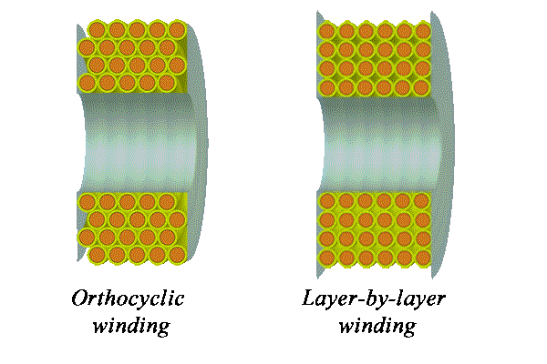 In this case, the winding turns out to be denser than the program considers, and with the same number of turns the inductance comes out less than the calculated one. This can be taken into account by introducing the coefficients of the relative pitch of the winding along the axis and along the radius. The idea was borrowed from the author of the CalcCoils program, for which special thanks to him. In the case of orthocyclic winding, the ratio pr / d ≈ 0.87. In addition, each winding machine has its own characteristics, which can be taken into account by the experimental selection of the winding density coefficients for a specific machine. In the case of mass production of coils, this makes the calculation more accurate. In this case, it makes no sense to take into account the thickness of the insulation.
The use of a litz wire for winding a coil can significantly reduce losses in it at the high-frequency end of the audio range. This is due to the reduction in heat loss in the coil due to the skin effect. Replacing a solid wire with a litz wire of the same diameter has not a significant effect on the value of inductance, therefore, litz wire winding is not taken into account in the program.
The use of air core coils in acoustic filters, due to their size, weight and high cost, makes sense only in Hi-End systems with a low level of distortion. In cheaper systems, the use of magnetic cores with an open magnetic circuit is allowed, preferably from materials with high saturation magnetization. The optimal winding for such coil is no longer a Brooks one. Its shape will depend on the parameters of the core. Calculation of such coils using simple formulas is impossible. Electromagnetic simulators such as ANSYS MAXWELL 3D must be used. With their help, you can not only calculate such a coil, but also calculate the optimal winding option for a specific core.
Related links:
- "DESIGN OF STANDARDS OF INDUCTANCE, AND THE PROPOSED USE OF MODEL REACTORS IN THE DESIGN OF AIR-CORE AND IRON-CORE REACTORS" - By H.B. Brooks 1931 (PDF);
- Brooks Coil and Calculator - NESS Engineering Inc.