Inductance calculation of a ferrite toroid coil
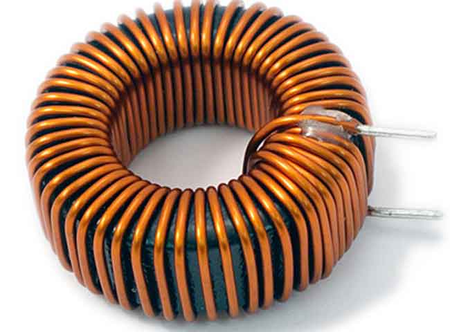
We can find the formula for the inductance of a rectangular cross-section toroidal coil step by step based on fundamental laws of electromagnetism. In accordance with the Ampere's Law, we can calculate the magnetic flux density in the core at an arbitrary distance r from its central axis.
 |
[1] |
The magnetic flux through the cross-sectional area of the core can be calculated as follows. We divide this area into infinitely thin segments of height h at a distance r from the axis and sum these segments by integrating over the radius:
 |
[2] |
Further, in accordance with the definition of inductance, we arrive at the following expression:
 |
[3] |
The signs in the formulas correspond to the following diagram of a toroidal ferrite core: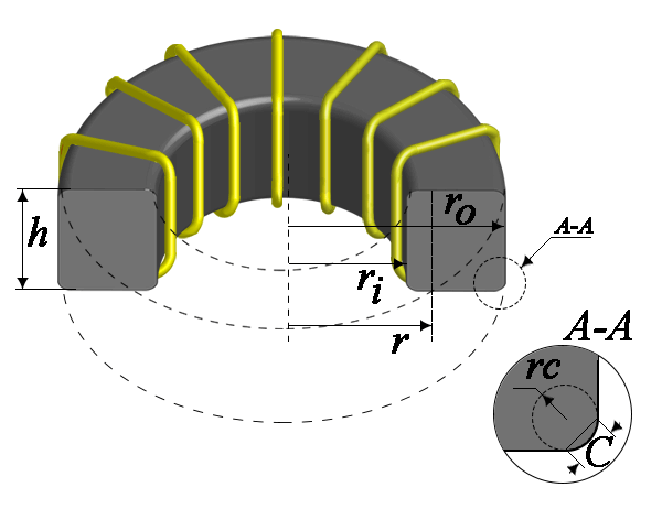
All of the above formulas use SI units.
- N - the number of turns of the coil;
- μ0 - magnetic constant 4π · 10-7 [T · m / A];
- μr - actual relative magnetic permeability of the core;
- I - the value of current through the coil [A];
- r - radius [m];
- ro - outer radius of the core [m];
- ri - the inner radius of the core [m];
- h - core height [m];
- L - inductance [H];
- B - magnetic flux density [T];
- ФB - magnetic flux [Wb];
In a simplified form, with the dimensions of the core in millimeters and the inductance in micro-Henry, the equation looks like this:
 |
[4] |
Where:
- L - the inductance of the coil [μH];
- h - the height of the ring [mm];
- OD - the outer diameter of the ring [mm];
- ID - inner diameter of the ring [mm];
- μr - relative magnetic permeability of the core;
The method for calculating magnetic core coils, which is standard, is recommended for use by the International Magnetic Association in IEC Publication 205, “Calculation of Effective Parameters of Magnetic Piece Parts”. In this method, the original core is substituted by an ideal toroidal core such that a coil wound on that toroid would give exactly the same electrical performance and with same number of turns as the original coil. The dimensional parameters of that substitute toroid are called effective parameters. These are indicated by the suffix "e" added to the symbol.
- Effective magnetic path length le [mm];
- Effective cross-sectional area of the magnetic circuit Ae [mm2];
- Effective core volume Ve [mm3];
The effective factors of a toroidal core with a rectangular cross section are determined as follows:
 |
[5] |
In these formulas, the dimensions ro, ri, he are in millimeters, C1 - mm-1, C2 - mm-3.
The chamfer is taking into account by the following expression:
 |
[6] |
In this expression, the actual core height h is substituted by its effective value he, which takes into account the presence of a chamfer C that reduces the total cross-sectional area of the core. In the absence of a chamfer (C = 0), the effective and actual heights of the core coincide he = h,
From the effective parameters of the core (do not forget about the dimensions in mm), the inductance can be found as follows:
 |
[7] |
The AL parameter, or the inductance factor of the core, can be found as follows (he in mm):
 |
[8] |
As can be seen from the comparison of the inductance calculation, which we derived from the fundamental laws of electromagnetism with the formula based on the effective parameters, the real ring core coincides with the ideal one in the case of a rectangular cross-section without a chamfer. Since almost all the magnetic flux is concentrated inside the core, and the magnetic circuit has no gaps, we can use the initial magnetic permeability of ferrite μi as μr, subject to a number of conditions:
- Ferrite core should work in low fields with a flux density much lower than the saturation flux density, at the initial part of the magnetization curve, more on this here;
- Ferrite core should work at a relatively low frequency at which the frequency dependence of the magnetic permeability can be neglected, more details here;
- The working temperature of the ferrite should be less Curie temperature;
- Ferrite core should work without the volume resonance phenomenon;