E core inductor calculations
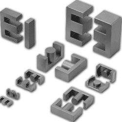 Ferrite cores for inductors have a wide variety species. E-shaped, U-shaped, pot cores of various modifications. Such cores are also used with the powder iron materials. Calculation of the coils with any ferromagnetic core uses method calculation with a special parameter AL - inductance factor of the core.
The basic calculation formula:
- L - inductance (nH)
- AL - inductance factor of the core (nH/turns square)
- N - number of turns of the coil
The parameter AL can be found in the manufacturer specifications for each species of core.
However, not all manufacturers publish AL values for their cores. In this case, you can calculate such a coil if you know the physical dimensions of the core and its magnetic permeability.
The method used Coil64 is recommended for the calculation of the dimensional parameters of E cores and is in accordance with IEC Publication 205, “Calculation of Effective Parameters of Magnetic Piece Parts.” For this method of calculating the dimensional parameters of E cores, the E core set is substituted by an ideal toroidal core such that a coil wound on that toroid would give exactly the same electrical performance as a coil with same number of turns placed on the E core set. The dimensional parameters of that substitute toroid. are called effective parameters. These are indicated by the suffix “e” added to the symbol.
- Effective magnetic path length le mm
- Effective cross-sectional area Ae mm2
- Effective core volume Ve mm3
A small reluctance of ferrite in comparison with air leads to the fact that almost the all magnetic flux is concentrated inside the ferrite core, forming a closed magnetic circuit. For the purpose of the calculation of the dimensional parameters, the closed magnetic circuit of the E core is divided into five sections. For each section the area and magnetic flux path length are determined.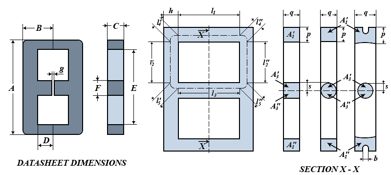
-
At the firs we find the initial dimensional parameters for the calculation from the reference datasheet dimensions. For the EE-core set::
h = B - D; q = C; s = F / 2; p = (A - E) / 2; - Magnetic flux path lengths [mm] of the sections and the corresponding cross-section areas [mm2] can be found by the following expressions:


- The core constants for the total magnetic circuit of the E core are:

- Now we can find the effective parameters le [mm], Ae [mm2], Ve [mm3] of the E core by the following formulas:

- To take into account the effect of the gap in the magnetic circuit, that has a high reluctance, the gapped core is substituted by a non-gapped one, with the same electrical performance and with the same number of turns. The magnetic permeability of such a core is called the effective magnetic permeability:
where µr is actual magnetic permeability of the core. When the coil is operating in the small signals mode, this value can be taken equal to the value of the initial magnetic permeability µi.
- At the finish we find the inductance of the E core coil set:
where:
- L - inductance [mH];
- µ0 = 4 π · 10-7 - the magnetic constant [H/m];
- µe - effective magnetic permeability of the core;
- N - the numbers of turns;
- Ae - effective cross-sectional area of the core [mm2];
- le - effective magnetic flux path length of the core [mm];
The µi spread of the core is quite high and depends on the temperature. The core dimensions are subject to manufacturing tolerances. The leakage of joint of the core halves is of great importance. Even with a very small gap, of the order of 0.01 mm, the effective magnetic permeability is much less than initial one. Therefore, due to these factors, the calculation of the E core coils by this method has a considerable error of up to ±30% and above and can be useful only for cores with unknown AL. For more accurate calculations it is necessary to use the AL factor, if you found it in the E core Datasheet.
Related links:
- Standard Specifications for ferrite U, E and I cores - The International Magnetics Association 2011 (PDF);
- Ferrite E-core online calculator;